
Precision in Every Steel Structure
Steel Fabrication Drawings
At Ahmed Construction Company, we understand that every steel structure starts with accurate and detailed drawings. Our Steel Fabrication Drawings are crafted to ensure seamless execution on site, minimizing errors and material wastage. Each drawing reflects real-world construction practices, helping our engineers and contractors bring your projects to life efficiently.Whether it’s structural beams, columns, trusses, or customized steel components, our drawings are clear, precise, and fully aligned with industry standards. By focusing on practical application, we make sure your steel fabrication process is smooth from design to installation.Call-to-Action (Optional): “Explore Our Steel Fabrication Drawings”
Steel Fabrication Drawings Services in Pakistan
You are building a steel factory in Faisalabad. A warehouse in Karachi’s industrial zone. A pre-engineered building in Lahore. Your structural engineer has designed the members. But your steel fabricator cannot start cutting and welding without steel fabrication drawings—detailed shop drawings that show every dimension, every bolt hole, every weld. Without accurate fabrication drawings, steel members are cut too short, bolt holes misalign, and connections fail. Consequently, fabrication waste increases (10-15% extra steel), site erection delays stretch into weeks, and structural integrity is compromised. At Ahmed Construction Company (ACCO), we provide professional steel fabrication drawings services in Pakistan that are accurate, fabrication-ready, and fully coordinated. For over 25 years, we have produced fabrication drawings for steel structures in textile mills, factories, warehouses, pre-engineered buildings, and industrial facilities for clients like Savour Foods and Gerry DNATA. From single-part drawings to NC files for CNC machines, our PEC-registered engineers deliver drawings that fabricators can use directly on the shop floor.
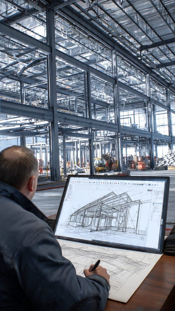
What Are Steel Fabrication Drawings?
Steel fabrication drawings (also called steel shop drawings or fabrication detail drawings) are detailed technical documents that steel fabricators use to manufacture steel components. Unlike structural design drawings (which show member sizes and loads conceptually), fabrication drawings show exactly: member cutting dimensions (precise length, camber, miters, copes), hole locations (bolt hole diameter, spacing, edge distance), welding details (weld type, size, length, location), material specifications (steel grade, section type—W, C, L, HSS, plate), surface preparation (priming, painting, galvanizing requirements), assembly marks (unique identifier for each piece, e.g., C1-2 for column 1 piece 2), and erection marks (where each piece goes on site). A complete fabrication drawing package includes: general arrangement (GA) drawings (overview of steel frame with mark numbers), single-part drawings (each individual member shown separately with all dimensions, holes, and cuts), assembly drawings (sub-assemblies like trusses, crane girders, stair strings), connection detail sheets (standard and custom connection details with bolt/weld specs), and cutting lists / material takeoffs (quantity of each section type, plate size, bolt count).
In Pakistan’s steel fabrication industry, accurate fabrication drawings are essential for: CNC machine operation (NC files drive automated beam lines and drill lines), material procurement (accurate takeoffs prevent over-ordering or shortages), quality control (each piece is checkable against its drawing), on-site assembly (clear mark numbers and GA drawings speed up erection), cost control (reducing rework and steel waste from 15% to under 2%), and coordination (clash detection with concrete, MEP, and architectural elements before fabrication).
ACCO’s steel fabrication drawings services in Pakistan include: 3D Tekla modeling, single-part and assembly drawing generation, NC (numerical control) file generation (DSTV format), connection detailing, bill of materials extraction, and PEC-registered engineering review. We serve steel fabricators, structural engineers, contractors, and industrial project owners nationwide.
Who We Are: ACCO – 25+ Years of Fabrication Drawing Excellence
For over two and a half decades, Ahmed Construction Company (ACCO) has been the trusted provider of steel fabrication drawings in Pakistan. From our head office at Office 2, 3rd Floor, Bigcity Plaza, Gulberg-III, Lahore, and our operational hub in Karachi, we have produced fabrication drawings for steel structures across Lahore, Faisalabad, Karachi, and all major industrial zones.
Our clients include steel fabricators, structural steel contractors, engineering firms, and industry giants such as Savour Foods, Gerry DNATA, and industrial project developers. What sets us apart is our use of Tekla Structures software—the global industry standard for steel detailing. We create fully detailed, 3D-modeled steel structures that allow us to: detect clashes (steel vs. concrete vs. MEP) before fabrication, generate single-part drawings automatically (reducing manual drafting errors), create NC files for CNC machines (enabling automated cutting and drilling), and extract accurate material quantities (for procurement). Consequently, our fabrication drawings reduce steel waste, eliminate field-fit problems, and speed up both fabrication and erection.
Learn more about our Architectural Engineering capabilities and Modular BIM Modeling services.
Our Steel Fabrication Drawings Services – Detailed Breakdown
We provide complete fabrication drawing packages for all types of steel structures across Pakistan.
1. Tekla 3D Modeling for Steel Fabrication
We create detailed 3D models of your steel structure in Tekla Structures. The model includes: all steel members (columns, beams, bracing, rafters, purlins, girts, crane girders, mezzanines), all connections (bolted and welded—moment, shear, pinned, bracing), all plates (base plates, gusset plates, stiffeners, end plates, cap plates), all bolts and welds (specified by grade, size, type), and all anchor rods/embedded plates (for concrete integration). The 3D model enables: clash detection (ensuring steel does not conflict with concrete foundations, MEP piping, or architectural finishes), visualization (client presentations, erection planning), automatic drawing generation (single-part, assembly, GA), and accurate BOM extraction.
2. Single-Part Drawings (Member Drawings)
We produce single-part drawings for every individual steel member in the structure. Each single-part drawing shows: overall length, cross-section profile (W, C, L, HSS, plate), cut angles (miters, bevels), copes and notches, hole locations (diameter, spacing, edge distance, bolt type), end preparations (square, beveled, coped), material grade (ASTM A36, A572, etc.), mark number (unique identifier, e.g., B-12, C-5), and weight. Fabricators use single-part drawings on the shop floor: cut to length, drill holes, weld attachments, and mark each piece with its mark number for site identification.
3. Assembly Drawings (Sub-Assembly Drawings)
We produce assembly drawings for sub-assemblies that are pre-fabricated in the shop before transport to site: roof trusses, crane girders, stair strings, platform sections, bracing assemblies, column tree assemblies, and rafter splice assemblies. Assembly drawings show: how individual single parts fit together, weld sizes at assembly joints, bolt locations (for field connections), assembly mark number (e.g., T-1 for truss 1), and assembly weight (for crane planning).
4. General Arrangement (GA) Drawings
We produce GA drawings showing the complete steel frame with all member mark numbers and connection references. GA drawings include: plan views (showing column and beam locations on grid lines), elevation views (showing vertical framing, bracing), section views (through complex areas), mark number reference lists (every mark appears in the GA), erection sequence notes, and reference to connection detail sheets. Erection crews use GA drawings on site to place each marked member in its correct location.
5. Connection Detail Drawings
We produce detailed connection drawings for every connection type in the structure: moment connections (welded flange plates, bolted webs—FEMA 350 compliant), shear connections (single/double angle, end plate, shear tab, seated), column base plate connections (anchor rod layout, grout details, stiffeners, leveling nuts), bracing connections (gusset plate with bolts and welds), beam splices (bolted or welded), and beam-to-beam connections (header and hanger connections). Each connection drawing shows: bolt sizes and grades (e.g., A325, diameter, type), weld symbols (AWS A2.4 – size, length, type—fillet, groove, plug), fit-up tolerances, and hole edge distances per AISC code.
6. NC (Numerical Control) File Generation for CNC Machines
For fabricators with CNC beam lines and CNC drill lines, we generate NC files in DSTV format directly from the Tekla model. The NC file drives the CNC machine to: cut steel member to exact length (±1mm), cope the end (flange copes, web copes) automatically, drill holes at precise X,Y coordinates, mill slots where required, and stencil mark numbers (paint or scribe) on the member for identification. NC files reduce fabrication errors by 80%, eliminate manual template marking, and speed up production by 30-40%. We also provide separate NC files for: beam lines (beam and cope data) and plate lines (plate cutting nesting).
7. Bill of Materials (BOM) & Cutting Lists
We extract from the Tekla model: steel quantity by section type (total weight of W sections, C channels, L angles, HSS, plates), bolt quantity by size and grade (count of each bolt type), weld length by type (total inches of fillet weld, complete joint penetration, etc.), surface area for priming/painting (square feet), and cutting lists (each individual member length and quantity). Fabricators use BOM for material procurement (ordering steel sections from suppliers) and cost estimation.
8. Pre-Engineered Building (PEB) Fabrication Drawings
For pre-engineered buildings (warehouses, factories, showrooms), we produce complete fabrication drawing packages including: main frame drawings (tapered columns and rafters with designer notes), secondary member drawings (Z and C purlins, girts—cold-formed or hot-rolled), bracing drawings (rod or angle cross-bracing), crane girder drawings (with rail attachment details), mezzanine framing drawings, and connection details (bolted splices, base plates, knee braces).
9. Connection Engineering & Stamp
Our PEC-registered structural engineers review all connection details for compliance with: AISC 360 (steel building code), RCSC specification for structural joints (bolted connections), AWS D1.1 (welding code), and seismic provisions (ductile detailing requirements for connections in high seismic zones). We provide calculation reports for non-standard connections and stamp drawings where required (typically for moment connections, base plates, and heavy bracing connections).
Comparison: ACCO vs. Typical Fabrication Drawing Providers
Many freelancers offer “fabrication drawings” but lack advanced software or engineering knowledge. Here is why ACCO is different:
| Feature | ACCO | Typical Freelancer / Small Shop |
|---|---|---|
| Software | Tekla Structures (global standard for steel detailing) + AutoCAD | Basic AutoCAD only – no 3D, no NC files |
| 3D Modeling & Clash Detection | Full 3D Tekla model with clash detection against concrete, MEP, architecture | 2D drawings only – clashes discovered during fabrication or erection |
| NC Files (DSTV) for CNC | Included – direct output to CNC beam lines and drill lines | Not available – manual hole marking, errors, slower production |
| Single-Part Drawings | Autogenerated from Tekla model – accurate, coordinated, each member has unique mark | Manual drafting – mark numbers missing, errors |
| Connection Detailing | Detailed moment, shear, base plate, bracing connections with bolt/weld specs, AISC compliant | Missing connection details or generic sketches |
| Engineering Verification | PEC-registered structural engineers review connections for AISC compliance | No engineering review – unsafe connections |
| Bill of Materials | Automatic extraction from Tekla – accurate quantities, steel tonnage, bolt counts | Manual takeoff from PDF – errors, waste, shortages |
| Fabrication Accuracy | NC files → CNC machines → ±1mm accuracy | Manual marking – errors, rework, field modification |
| Steel Waste | Under 2% with accurate NC files and cutting lists | 10-15% waste – significant cost on large projects |
| Revisions | 2 rounds of revisions included – model-based changes propagate to all drawings automatically | Charges extra – manual redrawing on each sheet |
| Turnaround Time | 2-3 weeks for typical industrial building (50,000-100,000 sq ft) | 4-6 weeks – manual drafting is slow |
| Client Support | Dedicated detailing coordinator (Mon–Sat, 9 AM – 6:30 PM) | Unreachable after payment |
| Nationwide Service | Lahore, Karachi, Faisalabad, all industrial zones | Local only |
Our Step-by-Step Steel Fabrication Drawing Process
We make steel detailing accurate, coordinated, and fast. Here is how we work:
- Step 1: Receive Structural Design Drawings – You send us structural design drawings (member sizes, loads, connection design). We also receive architectural and MEP drawings for coordination.
- Step 2: Tekla Model Setup – We set up a Tekla project: define grids (identical to architectural grids), create steel sections library, import reference files (architectural, MEP, concrete), and set fabrication standards (AISC, AWS).
- Step 3: 3D Steel Modeling – We model all steel members in Tekla: columns, beams, bracing, rafters, purlins, girts, crane girders, mezzanines, base plates, gusset plates, stiffeners, end plates, bolts (with grades and sizes), and welds (with sizes and types).
- Step 4: Connection Detailing – We detail all connections per design requirements and AISC standards: moment connections, shear connections (single/double angle, end plate, shear tab), column base plates, bracing connections, and beam splices.
- Step 5: Clash Detection & Coordination – We run clash detection in Tekla/Navisworks: steel vs. concrete foundations (anchor rods, embedded plates), steel vs. architectural (clear height, column locations), and steel vs. MEP (pipes, ducts, cable trays through steel beams). We resolve all clashes with the design team before fabrication.
- Step 6: NC File Generation – We generate NC files (DSTV format) for fabricators with CNC beam lines and drill lines. NC files control automated cutting, coping, and hole drilling.
- Step 7: Shop Drawing Generation – We generate from Tekla: single-part drawings (each member with full dimensions, holes, cuts), assembly drawings (sub-assemblies like trusses, crane girders), GA drawings (overview with mark numbers), and connection detail sheets.
- Step 8: Engineering Review & PEC Stamp – A PEC-registered structural engineer reviews all fabrication drawings for AISC compliance (member sizes, connection safety, bolt/weld capacities). We stamp drawings where required.
- Step 9: Delivery – We deliver: Tekla model (.tekla), fabrication drawings (PDF and DWG), NC files (DSTV), bill of materials (Excel). We include 2 rounds of revisions at no additional cost.
📢 Mid-Content CTA: Need Steel Fabrication Drawings for Your Project?
Stop manual drafting errors. ACCO’s steel fabrication drawings services in Pakistan include Tekla 3D modeling, NC files for CNC machines, and AISC-compliant connection detailing. Call +92 322 800 0190 or email info@acco.com.pk today. Mention “FAB” for a free consultation.
Why Steel Fabricators & Contractors Nationwide Choose ACCO
In Pakistan’s steel fabrication industry, inaccurate shop drawings are a costly problem. Fabricators receive incomplete sketches, leading to: members cut to wrong lengths (steel waste), bolt holes misaligned (field rework, requiring site drilling or re-fabrication), missing connection details (weld sizes not specified, leading to under-strength connections), and no NC files (manual marking is slow and error-prone). Consequently, projects are delayed, costs escalate, and stress increases for everyone involved.
ACCO has provided steel fabrication drawings in Pakistan for steel fabricators and contractors across Lahore, Faisalabad, Karachi, and other industrial zones. Our drawings are used by: large fabricators with CNC beam lines (who use our NC files for automated cutting and drilling), mid-size fabricators (who use our detailed single-part drawings with hole dimensions), and smaller shops (who appreciate our clear dimensions and cutting lists).
Furthermore, we serve clients nationwide. From Lahore to Faisalabad to Karachi, we provide steel detailing for all industrial sectors: textile mills (heavy crane girders, process platforms), warehouses (long-span PEBs), factories, pre-engineered buildings, and commercial steel structures. We also support steel fabricators working on projects in the UAE, UK, Saudi Arabia, Canada, and the USA.
Our integrated approach means we also provide architectural drafting and BIM modeling for complete project coordination. Explore our Architectural Engineering and Modular BIM Modeling pages.
By The Numbers: ACCO’s Steel Fabrication Drawing Track Record
- 5,000+ Single-part steel fabrication drawings produced.
- 1,000+ Assembly drawings produced (trusses, crane girders, platforms).
- 300+ Steel structures detailed (factories, PEBs, warehouses).
- 100,000+ Steel members detailed in Tekla 3D models.
- 10,000+ NC files generated for CNC beam lines.
- Zero Field-fit issues when NC files were used.
- 2% Average steel waste when using our NC files and cutting lists (industry average 15%).
- 100% AISC compliance for connection details.
- 25+ Years of continuous steel detailing practice in Pakistan.
- 2-3 weeks Average turnaround for typical industrial building (50,000-100,000 sq ft).
- 2 Offices (Lahore & Karachi) covering all industrial zones.
- 5+ Tekla-certified detailers on our team.
Frequently Asked Questions (FAQs) – Steel Fabrication Drawings
1. What is the difference between structural design drawings and fabrication drawings?
Structural design drawings (from a structural engineer) show member sizes, loads, and overall spans—they answer “what size beam do I need?” Steel fabrication drawings (from a steel detailer) show every hole location, weld size, cut dimension, and mark number—they answer “exactly how do I make this piece?” Design drawings are for engineers; fabrication drawings are for shop floor workers and welders. Both are needed for any steel project.
2. Why do I need Tekla for steel fabrication drawings?
Tekla Structures is the global industry standard for steel detailing because: it creates a 3D model so you can see clashes before fabrication (steel vs. concrete, steel vs. MEP), it automatically generates single-part and assembly drawings (saving weeks of manual drafting), it creates NC files for CNC machines (eliminating manual marking errors), it extracts accurate material quantities (preventing shortages or over-ordering), and it propagates changes throughout all drawings when revisions occur. ACCO uses Tekla for all steel fabrication drawing projects.
3. What are NC files and why do fabricators need them?
NC files (Numerical Control files in DSTV format) are digital files that drive CNC beam lines (automated saw and cope machines) and CNC drill lines (automated drilling machines). The NC file tells the machine: cut this beam to exact 12,345mm length, cope the left flange at these dimensions, drill 4 holes of 22mm diameter at X=200mm, Y=50mm from each end, and stencil mark number “B-12” on the flange. NC files eliminate manual marking, reduce fabrication errors by 80%, and speed up production by 30-40%.
4. What does a single-part drawing include?
A single-part drawing shows one individual steel member (e.g., column C-12 or beam B-8). It includes: overall length, cross-section profile (W12x65, etc.), cut angles (miters, bevels), material grade, hole locations (diameter, spacing, edge distance), end preparations (coped, square, beveled), a unique mark number (e.g., C12-2 for column 12 piece 2), and the member weight. Fabricators use single-part drawings to cut, drill, weld attachments, and mark each piece for site identification.
5. Do you provide connection engineering for moment connections?
Yes. For moment connections (fully-restrained connections that transfer both shear and moment), our PEC-registered structural engineers perform connection design checks per AISC 360: bolt shear and tension capacities, weld strength, column panel zone shear capacity, flange plate thickness checks, and ductile detailing for seismic applications. We provide calculation reports and stamp connection drawings where required.
6. How do I get steel fabrication drawings for my building?
First, you need structural design drawings from a PEC-registered structural engineer (member sizes, loads, connection design). If you don’t have design drawings yet, see our Architectural Engineering and Structural Drawings services. Once you have design drawings, send them to us—we will model in Tekla and produce fabrication-ready shop drawings with NC files.
7. What is the difference between single-part drawings and assembly drawings?
Single-part drawings show one individual steel member (one column, one beam, one brace). Assembly drawings show sub-assemblies made of multiple parts: a roof truss (made of many individual angles and gusset plates), a crane girder (with top and bottom flanges, web, stiffeners, rail), a stair stringer assembly (with treads, railings), or a column tree assembly (with column stub and attached beams). Assembly drawings are used by fabricators to weld sub-assemblies in the shop, then transport them to site for final erection.
8. Can ACCO provide steel fabrication drawings for pre-engineered buildings (PEB)?
Yes. We have detailed pre-engineered buildings for warehouses, factories, and showrooms. Our PEB detailing includes: main frames (tapered columns and rafters with designer notes), secondary members (cold-formed Z/C purlins and girts with standard hole patterns), bracing (rod or angle cross-bracing), mezzanine floors, crane girders (with rail attachment details), and connection details (bolted splices, base plates, knee braces). Our detailing is compatible with major PEB manufacturers’ fabrication standards.
Get Fabrication-Ready Steel Drawings – Choose ACCO
Your steel structure is only as good as its fabrication drawings. Poor drawings lead to: members cut to wrong length (steel waste), misaligned bolt holes (field rework, production delays), missing weld sizes (weak connections), and no NC files (manual marking errors). Therefore, investing in professional steel fabrication drawings is not a cost—it is an investment in fabrication efficiency, steel cost savings (reducing waste from 15% to under 2%), and on-time project delivery.
ACCO has been providing steel fabrication drawings services in Pakistan for over 25 years. We are trusted by steel fabricators, contractors, and industrial project owners. Our Tekla-powered process delivers 3D modeled, clash-detected, NC-file-ready fabrication drawings that fabricators can use directly on the shop floor—whether they have CNC machines or manual equipment.
We serve all major industrial zones nationwide: Lahore, Faisalabad, Karachi (SITE, Korangi, Port Qasim), Multan, Sialkot, Gujranwala. We also support international fabricators and contractors working on projects in Pakistan with headquarters in the UAE, UK, Saudi Arabia, Canada, and the USA.
Ready to get fabrication-ready steel drawings? Contact ACCO today. Your Tekla model, NC files, and shop drawings could be ready in two weeks.
Alternate: +923 111 749 849
✉️ Email your structural design drawings: info@acco.com.pk
🏢 Visit Us: Office 2, 3rd Floor, Bigcity Plaza, Gulberg-III, Lahore (near Kalma Chowk)
🕒 Working Hours: Monday–Saturday, 9:00 AM – 6:30 PM
→ REQUEST A FABRICATION DRAWINGS QUOTE ←
ACCO – Precision Steel Fabrication Drawings. Since 1998.
Explore related services: Learn about our Architectural Engineering integration or view our Our Projects gallery to see our steel fabrication drawings in action.